BLIKVM v2 PCIe
Introduction
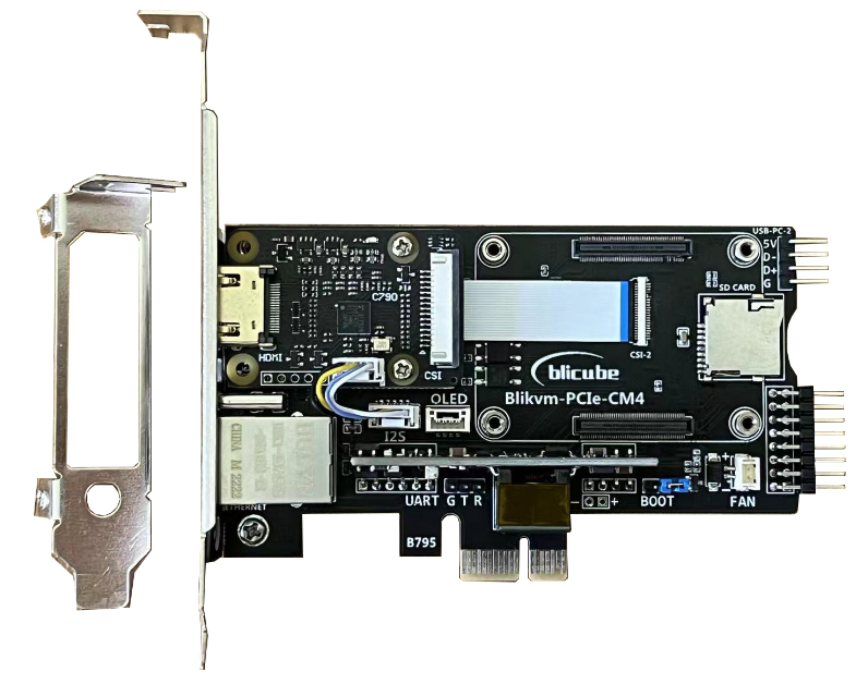
BLIKVM PCIe is a PCIe add-in card based on Raspberry Pi CM4 for KVM Over IP. This product’s key features include video capture, ATX controller, PoE, OLED , UART and RTC. The card has a standard PCIe I/O bracket and a low profile PCIe I/O bracket. The product is currently perfectly compatible with blikvm image and pikvm image.
Installation requirements
- Raspberry Pi CM4(if you order PCIe card only).
- PoE-sourcing equipment or 5V/3A USB adapter.
- CR1220 coin cell battery.
Features
- Video capture (HDMI, support 1080P@60Hz input)
- Keyboard forwarding
- Mouse forwarding
- Mass Storage Drive
- ATX Control the server power using ATX functions
- Fullscreen mode
- Access via Web UI
- Support multi language switching
- Support PoE
- Serial console port
- OLED display
- Real Time Clock (RTC)
- PWM Fan
Basic setup
- If you have an assembly kit, Flash the memory card or eMMC
- Build BLIKVM according to the illustrated instructions:
💡 Geerling: Engineering Test video
💡 Craft Computing: Never Pay For IPMI Again - BliKVM Review
Specification
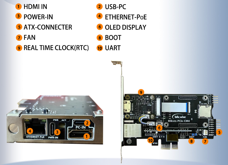
| 1 | HDMI in | 2 | USB-PC port |
|---|---|---|---|
| 3 | Power Input 5V 3A | 4 | RJ45 1000M Ethernet port & PoE |
| 5 | ATX control port | 6 | OLED Display |
| 7 | PWM FAN | 8 | BOOT |
| 9 | REAL TIME CLOCK(RTC) | 10 | UART port |
| 11 | USB-PC port |
The bridge chip is Toshiba TC358743, which supports both video and audio(I2S), and the highest input resolution is 1080p@60hz. Fixed HDMI back power issue.
The BLIKVM PCIe card provides two USB interfaces, one is PC-IN (type c interface) and the other is USB-PC2 (pin interface). The purpose of these two interfaces is to connect to the USB of the controlled computer, used to control the mouse and keyboard. At the same time, only one interface can be used. The purpose of designing two interfaces is to directly use USB PC2 when the user's PC host has a row pin USB interface, which will make the wiring more concise.
When using PoE power supply, there is no need to connect the PWR-IN port. When not using PoE power supply, connect the PWR-IN port to a standard 5V/3A USB power supply.
- Gigabit Ethernet port
- Standard: IEEE 802.3af PoE
- Input voltage: 37-57 V DC
- Output power: 5 V DC/2.4 A
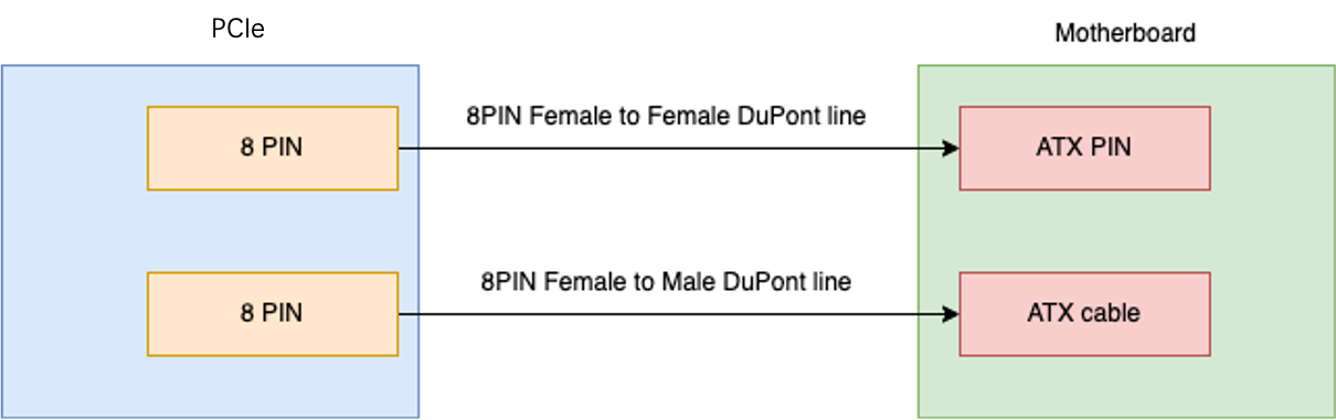
- Connect to power control interface on the motherboard of the controlled computer with DuPont cables. It can turn on, off, and restart the controlled computer.
- The pin is defined on the printing of the PCIe board, BTN means button.
- According to the instructions of the computer motherboard, first find the position of the ATX function related pins on the motherboard, and then unplug the ATX ray that has been connected to the motherboard. After unplugging, the power button of the computer will lose its function. There are two rows of 8PIN pins on the PCIe board. It is unnecessary to distinguish between the two rows of pins when they are used with the same functions. One row of pins is used for KVM to control ATX-related functions, and the other row of pins is connected to the ATX DuPont head unplugged from the main board to maintain the original chassis power button function. Connect each wire according to the specific pin definitions on the motherboard and PCIe. See the following figure for the connection relationship:
A white OLED display with a resolution of 128x64, and the chip is SSD1306. This display can show the temperature, IP address and other information of the Raspberry Pi.
The Card HAT is fitted with a small fan that is controlled by your Raspberry Pi CM4 via GPIO12.
Fit jumper to disable eMMC Boot
The clock chip is PCF8563 that is controlled by your Raspberry Pi CM4 via I2C. The CR1220 battery is installed under the HDMI IN module.
Connect the serial port to debug your Raspberry Pi CM4.
The uart of Raspberry Pi CM4. G for GND, T(GPIO 14) for TXD, R(GPIO 15) for RXD.
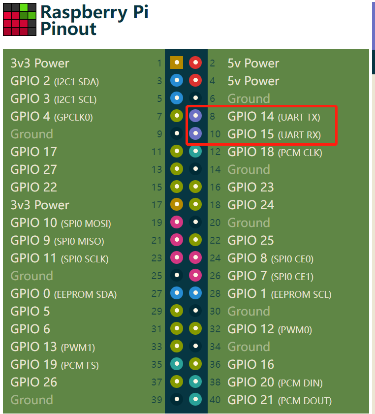
Connect serial cable wires to G T R connectors on the PCIe board. NOTE: black wire = Ground, whiTe = Tx, and gReen = Rx; For specific methods, please refer to this document.
Accessories
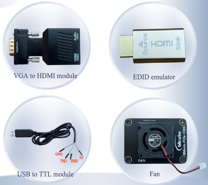
If the controlled computer does not output HDMI images correctly, please use this accessory. Connect the Source port to the controlled computer, connect the Sink port to the HAT. Then you can set the correct HDMI output on the controlled computer.
When your device does not have an HDMI output interface, you can use a VGA to HDMI module.
Connect your computer usb interface with the serial port of BLIKVM to debug your Raspberry Pi CM4.
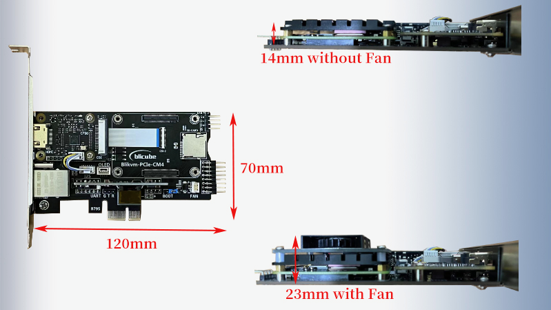
Use a cooling fan to cool the Raspberry Pi CM4, but installing a fan will make the product thicker than a standard PCIe add-in card.
Dimensions
Test Video
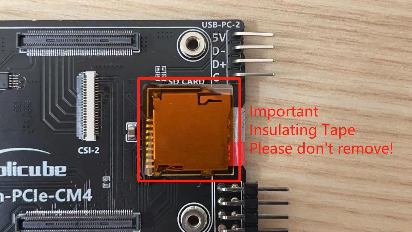
Notes
List
Product List
| BLIKVM PCIe card version | 1 |
|---|---|
| BLIKVM PCIe add-in card | 1 |
| Cooling fan | 1 |
| OLED display | 1 |
| USB to TTL module | 1 |
| HDMI pass-through EDID emulator | 1 |
| VGA-HDMI module | 1 |
| 32G Micro SD card | 1 |
| HDMI cable 0.5m | 1 |
| HDMI Coupler | 1 |
| Network cable 1m | 1 |
| USB-A to USB-C cable 1m | 2 |
| Dupont USB cable 0.4m | 1 |
| WiFi antenna | 1 |
| Dupont Cables 8pin Male to Male 40cm | 1 |
| Dupont Cables 8pin Male to Female 40cm | 1 |
| Metal heatsink | 1 |
| Phillips screwdriver | 1 |
| Cross Wrench Sleeve | 1 |
| BLIKVM PCIe plug-n-play version | 1 |
|---|---|
| BLIKVM PCIe add-in card | 1 |
| CM4 102000 | 1 |
| Cooling fan | 1 |
| OLED display | 1 |
| USB to TTL module | 1 |
| HDMI pass-through EDID emulator | 1 |
| VGA-HDMI module | 1 |
| 32G Micro SD card | 1 |
| HDMI cable 0.5m | 1 |
| HDMI Coupler | 1 |
| Network cable 1m | 1 |
| USB-A to USB-C cable 1m | 2 |
| Dupont USB cable 0.4m | 1 |
| WiFi antenna | 1 |
| Dupont Cables 8pin Male to Male 40cm | 1 |
| Dupont Cables 8pin Male to Female 40cm | 1 |
| Metal heatsink | 1 |
| Phillips screwdriver | 1 |
| Cross Wrench Sleeve | 1 |
List of items prepared by the user
| Raspberry Pi CM4(if you order PCIe card only) | 1 |
|---|---|
| PoE-sourcing equipment or 5V/3A USB adapter | 1 |
| CR1220 coin cell battery | 1 |